Description:
Project description
The goal of this project was to explore how to integrate digital sound synthesis within the hardware of the existing T-Stick digital music interface(DMI). To achieve this, I have developed embedded code for a digital synthesizer, which runs on the ESP32 microcontroller inside the T-Stick.
This project was undertaken for MUMT 502 Senior Project: Music Technology, supervised by Professor Marcelo Wanderley. I also received additional advice and assistance from Travis West, who is one of Professor Wanderley’s PhD students, and from other members of the Input Devices and Musical Interaction Laboratory(IDMIL). This report aims to document my process developing this project and the issues and setbacks I faced during it, to help future implementations of embedded synthesis avoid the problems I have encountered.
Considerations
One of the first and most important decisions to be made for the project was what additional hardware would need to be added to the T-Stick in order to add embedded synthesis. Specifically, I needed to determine what microprocessor board I would be using to compute the digital synthesis, as well as what types of digital to analog converter(DAC) and amplifiers would be used for the audio output.
In determining the microprocessor board I wanted to use, I considered a number of options including the Teensy 4.1, the Raspberry Pi Pico, the Raspberry Pi Zero 2 and the ESP32. Of these, the ESP32 had the advantage of already being present in the T-Stick, whereas the others would require adding an additional board into the fairly limited space of the T-Stick interior. However, this requires the synthesis code to share resources with the other processes already running on the T-Stick controller.
Chip comparisons
Teensy 4.1
The Teensy 4.1 is a high power microcontroller board which has very well established support for audio programming and processing through the use of an external shield with DAC and amplifier capabilities. Teensy offers a software library with
As well, the microprocessor used by the Teensy contains inbuilt special operations for audio processing, allowing for hardware acceleration of common digital signal processing tasks. In this case, however, the computational complexity of the synthesis performed was low enough that this would not have been of assistance unless further options for filtering and adding effects to the synthesized sound were added.
One additional possibility that I did not explore was attempting to use the Teensy audio shield as an external board for the ESP32 instead. Given the lack of good alternatives for audio generation boards, it may have proved a convenient solution.
Raspberry Pi Pico
The Raspberry Pi Pico is a microcontroller board which is available for very low cost and which can be used as a medium power microprocessor with a wide variety of different software environments. It features support for the Arduino and Micropython software ecosystems, as well as a C++ SDK. It does not have in-built audio support, but can interface with an external DAC over I2S.
Raspberry Pi Zero 2
In comparison to the other boards, the Pi Zero is a full-blown microcomputer capable of running a full operating system and connecting to standard computer peripherals. As a result, it has by far the highest processing power and supports a wide range of audio software, but it also lacks an effective way of outputting audio for our purposes. By default, the hardware only supports providing audio output via USB or an HDMI connection, both of which would be very difficult to integrate with other musical audio equipment. As well, it has a substantially higher power consumption and heat production than the other boards it is being compared against, neither of which are ideal for the T-Stick environment.
ESP32
The ESP32 is a ubiquitous microcontroller which features a relatively powerful dual core processor and a number of Wifi and Bluetooth capabilities. It has a well-established and well documented SDK for C++ development on the board, ESP-IDF. Furthermore, the Sygaldry software framework we make use of was developed for the ESP32 (although support was extended to other boards during the time span of my project). It also has a built-in DAC and support for the I2S protocol, both of which were used over the course of the project.
The ESP32 controller was ultimately selected because there is already one built into the T-Stick hardware, and because it has enough computing power that it can effectively run both the synthesizer and instrument processes at the same time. Other boards that could have potentially been used would have required either fitting another board in the already fairly confined T-Stick casing, or adding an external expansion for producing audio output. As well, only the Teensy or Raspberry Pi Zero would have more power available to them than the current ESP32 board.
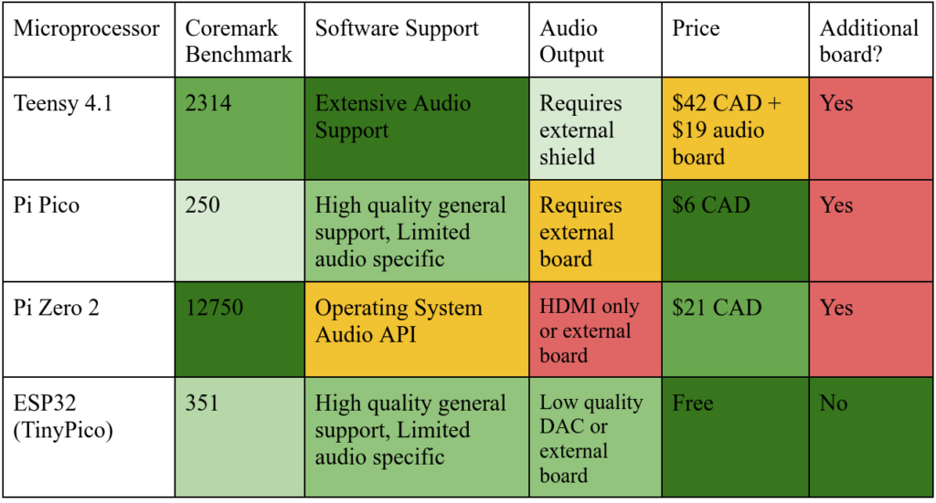
A table comparing the different possible processors for the project and their benefits on various axes.
Audio pipeline options
Once synthesis is performed on the ESP32, we need a way of converting the digital samples to an analog audio output. This requires a series of decisions regarding the DAC hardware used, and the protocol used to communicate with it. Over the course of the project, I considered three different protocols for outputting audio from the ESP32: I2C, I2S, Bluetooth, and working directly with the in-built DAC.
I2C
The I2C protocol is a ubiquitous general communication protocol for microcontrollers to interface with external electronics. It is well supported by software libraries, including both the ESP-IDF and the Sygaldry framework. It is not especially difficult to source DACs which take an I2C input. However, it is also a substantially more complex protocol than I2S, and most devices only support it at a communication speed (400 kbps) which is too low to transmit audio signals at an acceptable sample rate.
I2S
The I2S protocol is an audio-specific protocol for communication between audio devices. It has support implemented in ESP32-IDF, and can run at high sampling rates without substantial difficulty. As well, it was easy to source an external DAC board, the MAX98357A, that takes in I2S data and can directly drive a speaker output (although its performance left much to be desired, as I will discuss). However, it was difficult to source other DACs which would accept an I2S input, aside from the first model tried. Furthermore, it was a difficult protocol to debug given the sensitivities in its timing and the protocol being designed for on-board communication, not wired transmission, and was a source of many mysterious issues throughout the development of the project.
Raw DAC
Although it’s arguably not an actual protocol, we can drive the in-built DAC of the ESP32 directly from the software to produce an audio output. This has the advantage of being fairly reliable and not requiring any external hardware, but it comes at the cost of having to work with the ESP32 system at a lower level compared to the I2S API, as well as a substantially lower audio quality. As well, it is more sensitive to timing issues with the multiple threads running on the ESP32, and more sensitive to general electrical noise within the system.
Bluetooth
The ESP32 is inherently designed for Bluetooth, and as such has an established support for streaming Bluetooth audio output. This would allow for the T-Stick to be fully wireless while still capable of producing audio output. It would also mean that no additional hardware would be required. However, it would also lead to a substantial increase in the complexity of the software, and Bluetooth audio has both noticeable latency which is unacceptable for musical performance, and applies compression which lowers the quality of the audio produced.
Process
Initial design
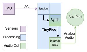
I decided fairly early on in the project that I would implement the synthesizer as a wavetable synth, with four different wavetables which could each have their pitch and volume individually controlled. The initial plan was for the synthesizer to work by using the I2S(Inter-IC Sound) protocol to send samples from the software on the ESP-32 to an external DAC and amplifier board, the MAX98357A. To prevent lag in the audio output, the I2S communication loop had to run in a separate thread from the main instrument, which I managed by having the main instrument thread control the parameters through a pair of state objects.
A diagram of the original planned structure of the T-Stick augmented with embedded synthesis.
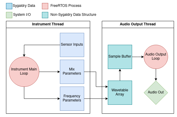
A diagram of the structure of the software implementation of the embedded synthesizer showing the data structures and processes involved, and the two separate threads and how they interact with each other.
The Sygaldry library allowed the synthesizer implementation to interface with the other components of the T-Stick in a modular way. I implemented the wavetable synthesizer as just another Sygaldry component, which is included in our new copy of the T-Stick firmware. In the main loop it would modify the properties of the inactive copy of the object, and only once this is complete could it switch it with the active one. Otherwise there would have been issues with adjusting the synthesizer parameters while it was in the middle of outputting samples.
Issues
I2S audio
Almost immediately once I advanced far enough in the project to be able to start producing sounds from the ESP32, I ran into extreme issues with distortion and noise in the audio playback to the point of the intended sound being unrecognizable. I would analyze the sound output by looking at its spectrum while trying to play a pure tone, and found that while it would contain a component at the desired frequency, it would be overpowered by semi-evenly spaced non-harmonic components at higher frequencies. As well, there would be a low frequency “beating” in the sound produced, visible as a grid-like structure in the spectrogram.
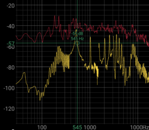
The frequency spectrum produced by the MAX98357A driving a small speaker. Notice the peak around our desired frequency (540Hz), alongside the additional distorted harmonics.
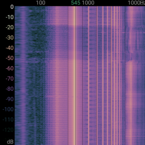
The spectrogram of the same audio, showing once again the unintended over (and under) tones, as well as the regular beating effect in the sound produced, which has the appearance of a grid in the spectrogram.
To further debug this issue, I set up a system where I would use an external Raspberry Pi Pico running an Arduino implementation of the I2S protocol. From there, I would monitor both the samples that the ESP32 believed itself to be outputting based on the synthesizer implementation as well as the samples that the Pi Pico believed itself to be receiving. There was shockingly little correlation between these two sets of samples. This caused me to believe that the issue lay somewhere between my implementation calling the ESP-IDF functions to send I2S data and the data itself being sent out through the wires to the Pi Pico receiver.
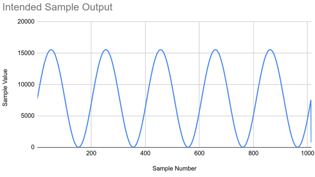
A graph of the samples that the synthesizer implementation believed itself to be sending to the I2S receiver.
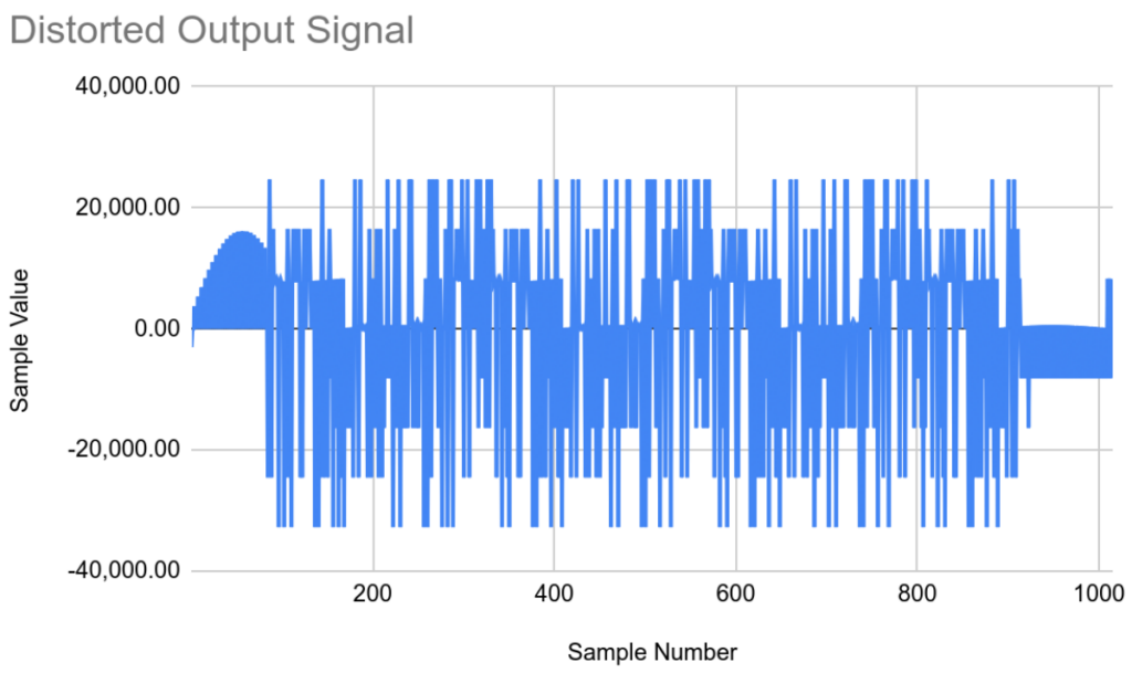
A graph of the samples the I2S receiving device I created believed itself to be receiving. Note the partially intact sign wave at the beginning, before the signal becomes completely chaotic.
Concerned about this, I was able to bring my system in for testing in the IDMIL lab and make use of the better testing equipment and receive help from Travis West in debugging the problems with the audio. With the help of him and a proper logic analyzer, I discovered that in fact the system was properly outputting the I2S signals as I intended them to be. This led us to instead suspect that there may be a mismatch between the format of the I2S data output by the ESP32, and the one expected by the MAX98357A, since the I2S protocol has three slightly different formats that data can be sent in. These formats correspond to bit-shifts of the samples, or differences in the start and end of each clock cycle. However, we realized that the board was designed to automatically detect and switch to the proper format, and that the numerical errors I was seeing previously did not correspond to the kinds that would result from bit shifting or mistiming.
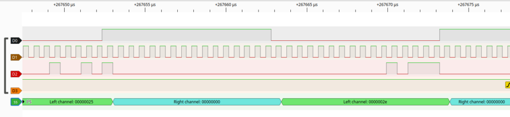
The logic analyzer output, showing that in fact the I2S output of the device was correct.
We decided to connect the outputs of the MAX98357A to an oscilloscope to see what was happening to the audio output directly. The result was that we were adjust it in order to make out the rough structure of the intended signal, but with a massive amount of noise and interference that should not have been present. This caused us to conclude that the issue was fundamentally with the MAX98357A board. This could have been due either to a fault or damage of the specific board I was using, or perhaps there being a systemic issue with that model that we encountered for some reason. Regardless, due to difficulties sourcing another appropriate I2S-based DAC board and especially one that would ship before the end of the semester, I elected to transition the project to instead use the builtin DAC of the ESP32. This resolved the issues with the audio output being distorted.
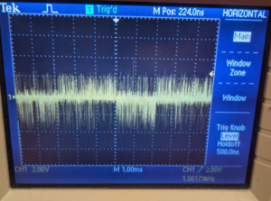
Photo of the oscilloscope display, showing the heavily distorted result of trying to play a square wave.
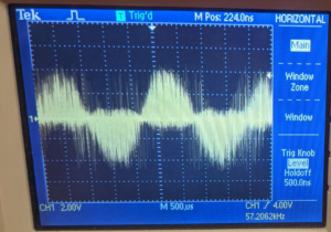
A photo of the oscilloscope output showing the distorted result of trying to play a sine wave.
Timing/unwanted FM
Throughout the project I have also faced some issues with irregularity in the output signal that seem to emerge from timing issues within the software implementation of the synthesizer. This comes in the form of two different noticeable effects, occasional “click” noises in the audio output and also an unintended frequency modulation effect which produces noticeable overtones in the spectrum of the output sound even when working with pure tones. Specifically, I believe they come from two things: mismatches in the two independent threads running in the program, and accidental misalignment of the sample buffers sent to the output. My reason for thinking this is that in the former case, by deliberately inserting delays into the bodies of the two different main loops, I get a noticeable difference in the frequency in which the errors occur. Perhaps both fortunately and unfortunately, this issue has become less pronounced as I have switched to using the inbuilt DAC of the ESP32 and refined the audio configuration. This has reduced the overall magnitude of the issue, but has also made it harder to track down and isolate.
In the future, I think fine tuning and extensive debugging of the timing relationship between the two main threads would be able to solve this issue. However, due to the amount of time previously spent debugging I2S issues (which at the time I thought this issue may have just been another manifestation of), I did not have time to do so in this project. As a result, in the final product there are noticeable occasional errors in the audio output, although they are much harder to notice than they were earlier in the testing phase.
Final Product
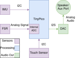
A diagram showing the updated structure of the final implementation.
Due to lacking the time to figure out a new I2S-based DAC, I decided to instead redesign the audio pipeline to make use of the DAC inbuilt to the ESP32. The DAC was wired directly to a 3.5mm audio jack, and was able to produce a strong enough output to effectively drive a pair of headphones or a stereo system. The result of this is that the current T-Stick design can be augmented with an inbuilt synthesis and audio output capability with the addition of only one new component(the audio jack) being wired to the TinyPico. Due to a lack of time, and the input system not being a focus of the project, I elected to not include the touch sensing capabilities of the T-Stick within my implementation. Instead, as a proof of concept, I chose to focus on an entirely IMU based control scheme.
Synthesizer Description
Throughout the project, the design of the synthesizer implemented remained quite stable. The synthesizer is set as an array of four wavetable oscillators, by default set to a sine wave, square wave, saw wave and noise. Each of these wavetables can have a pitch set individually (the noise channel is generated by adding randomness on top of the saw wave, so it has a weakly perceptible pitch), and has controllable mix levels.
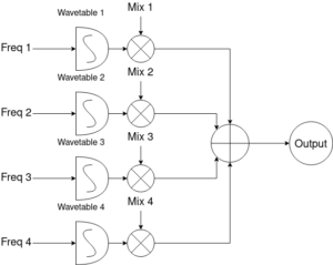
A signal flow diagram of the simple wavetable synthesizer.
This configuration allows for producing a wide variety of sounds at multiple different pitches, and with different wavetable configurations can recreate a large number of different sonic textures.
Input mapping
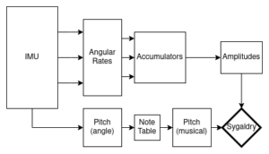
A diagram showing the general structure of the control scheme implemented.
The control scheme for the synthesizer was not a primary focus of this project. However, for the purposes of demonstration I still put a system in place for controlling the synthesizer in a way similar to existing ways of controlling the T-Stick. For the sake of simplicity, I decided to implement a system of controls based entirely on the IMU. This system works by reading the IMU output to obtain both the absolute pitch(as in vertical angle) of the instrument as well as its current angular rate on each axis. The angular rates are fed into leaky accumulators, implemented as an array of values which at each step of the instrument control loop have the absolute value of the current angular rate added to them, but which also decay at an exponential rate. This allows for the detection of broad sweeping gestures, reminiscent of swinging a sword or (more realistically) playing an early Wii game. The absolute pitch of the instrument is used to control the musical pitch of the tones playing, however this only occurs if the system detects a sufficient twisting motion on the roll axis. This allows you to “lock in” a tone, and then play it by swinging the device on its other two axes. As well, while the pitch (musical) is derived from the pitch (angular) of the instrument, it is quantized to fit to the nearest note on the musical scale.
Assessment
Failures
The area in which this project was least successful was in finding an appropriate method of outputting audio from the ESP32. The inbuilt DAC solution I chose in the end is effective enough for a proof of concept, but the quality remains lacking compared to what would have been possible if the I2S based solution was successful. In my opinion, this is the most important problem to be resolved for future work in this area. Finding a reliable combination of software support, protocol and hardware is key to an embedded synthesis project succeeding. As well, while the audio artifacts caused by the timing and synchronization between threads remained an issue until the end of the project, although it did substantially improve, future work would need to determine how to fully eliminate this issue. Specifically, I believe a large amount of testing how different parameters and refactorings of the code affects the audio signal output would provide the necessary information
to isolate and resolve the root cause of the issue.
What’s missing
Due to limitations of time, there were a number of aspects of full integration into the T-Stick that I was not able to complete within the course of the project. I was not able to explore the physical modifications of the T-Stick hardware necessary to fully integrate embedded synthesis into the design, such as modifying the 3D-printed endcaps to support an audio output jack, and fitting additional hardware and wiring into the circuitry of the instrument. As well, in the interest of a simpler interface for interaction with the instruments, I did not make use of, or implement in my testing, the touch sensor used in the T-Stick. In future projects, I think the touch interface would be effective as an additional control scheme for controlling effects applied to the existing sound output of the instrument.
Successes
The most successful part of this project was how easy it was to implement the software for the synthesizer on the ESP32. Throughout the project, the issue was almost never that it was producing the wrong samples for playback, rather it was getting those samples properly translated to audio. The computational resources of the ESP32 were more than adequate for the system implemented, and from my testing I believe the system could scale to larger or more wavetables, higher precision samples or a more complicated synthesizer architecture without substantial difficulties.
As well, integrating the synthesis capabilities into the Sygaldry software was effective, aside from the timing issues between threads which would be an issue regardless of whether we were using Sygaldry or not. It was fairly straightforward to add the synthesizer as a new component that could be included in a Sygaldry instrument and easily controlled through the interfaces that Sygaldry automatically defines from its inputs.
Relating to that point, it was easy to implement a system for controlling the synthesizer based on the input methods available from the T-Stick. It took very little additional effort to set up a control scheme that maps from the controls to the input parameters of the synthesizer, and to do so in a modular way that could easily be reconfigured.
Code
The code is available here.